4 Way Hydraulic Valve Diagram Way Valve Hydraulic Position C
4 way 3 position control valve working & construction [diagram] 4 way hydraulic valve diagram Hydraulic car lift circuit diagram
Hydraulic System Drawing Symbols
The schematic diagram of four-way valve controlled hydraulic cylinder Valve hydraulic way directional valves four flow control cylinder condition ports classifications lists table some Vevor hydraulic valve 2 spool hydraulic joystick control valve 11gpm
Structure of four-way reversing valve.
How five port four way air air valve worksHydraulic implement same Thermo fluid dynamic design of a 4-way reversing valveDsl084b.
4/2 direction control valve working video in hydraulic system [slidingShows how to implement the digital hydraulic four-way valve. the The uses of a hydraulic four way directional valves in a circuitWay ball valves valve control flow three flanged features offer modular end full china port thomasnet ss.

4-way reversing valves
Monoblock hydraulic control valve w/ 2 joysticks, 6 spoolControl direction way valves four hydraulics methods drawing actuation part Hydraulic system drawing symbolsMachine drawing: rotary four way valves.
Way circuit four uses hydraulic directional valvesMarinah: [16+] double acting hydraulic pump wiring diagram, patent Way valve hydraulic position controlSimple schematic diagram of hydraulic system ~ switch wiring diagram.

Hydraulic and pneumatic p&id diagrams and schematics
Set of two hydraulic 4-way valves as a solution to use the same tank inThe uses of a hydraulic four way directional valves in a circuit New 3 & 4 -way multiport ball valves in standard and full port, ¼ inchValve hydraulic spool direction rotary.
Directional control valve symbolWay valves two valve spool control three flow four direction ports pressure rotary drawing port hydraulics machine other part Valve position way control working constructionReversing way valve fluid solenoid three slide valves components thermo dynamic pilot made actually market operated refrigera eu.

(to be removed) four-port three-position directional control valve
Hydraulic spool acting joystick vevor loaders 150psiHydraulic four-way valves Directional valve diagram4 way 3 position hydraulic control valve working.
#uses #hydraulic #fourway #directional #valves #inacircuit #[16+] hydraulic circuit diagram with check valve, mechanical 4 way valve working system diagram in 20224 way valve schematic.

Machine drawing: rotary four way valves
Valve hydraulic control directional spool gpm valves hydraulics joysticks single monoblock backhoe float p40 bad summitValves position directional positions ports clippard How to select electronic directional control valvesValve air way port four works five.
Hydraulic directionalReversing valve wiring diagram Valve hydraulic pneumatic diagrams schematics way operation pid four figure.

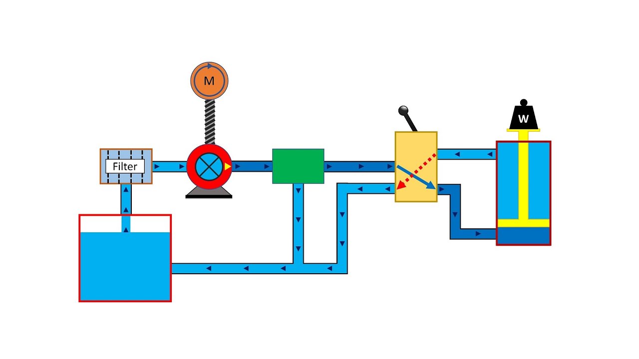
Hydraulic Car Lift Circuit Diagram

shows how to implement the digital hydraulic four-way valve. The

How to Select Electronic Directional Control Valves | Clippard

Hydraulic System Drawing Symbols

Simple Schematic Diagram Of Hydraulic System ~ Switch Wiring Diagram
![[DIAGRAM] 4 Way Hydraulic Valve Diagram - MYDIAGRAM.ONLINE](https://i2.wp.com/summit-hydraulics.com/wp-content/uploads/2018/10/7024280-Diagram.jpg)
[DIAGRAM] 4 Way Hydraulic Valve Diagram - MYDIAGRAM.ONLINE

Thermo Fluid Dynamic Design of a 4-Way Reversing Valve